iotrap.
Rabbits are an invasive pest and destroy a significant amount of crops every year. The problem is widespread with 57% of farmers losing crops to rabbits and 62% attempting some form of rabbit control. Current rabbit-trap solutions are labor intensive, do not provide metrics on usage, and provide no remote communication regarding the activation status of individual traps. For our third year engineering design project, our group created a smart, IoT-enabled rabbit trap.
Members: Ali Vira, Daniel Schwarz, Graham Bleaney, Julian Man, Matthew Kuyzk, Michal Ulman
Designed Solution
An iterative design process was employed to arrive at the final prototype. Existing state of the art solutions were analyzed to learn about the problem space. A problem statement was defined and users were identified. Farmers were interviewed and research was further conducted by investigating academic journals. Primary, secondary, and latent needs were identified. An IoT-enabled trap was selected as the optimal design on which to iterate. Concepts to satisfy the user needs were generated and tested. Four main questions were considered during the testing phase.
- Can the location of the trap be encoded?
- Can the trap communicate with a central computer
- Can the trap power the transmitter?
- Does the trap still work?
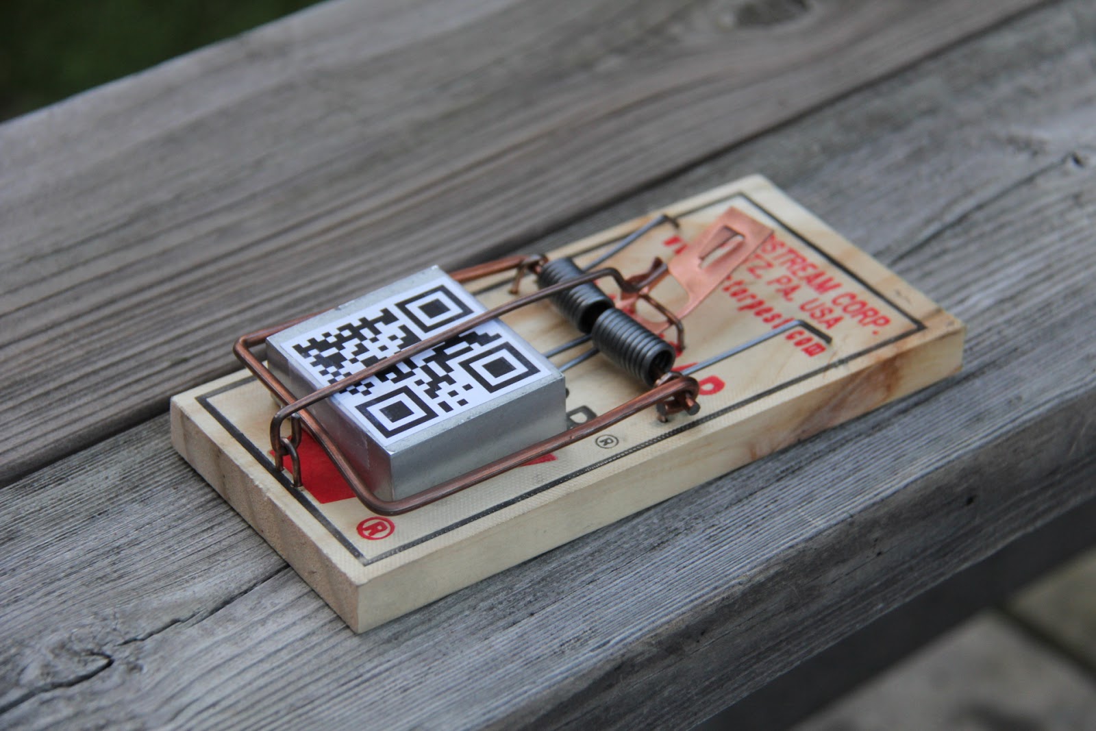
Hardware
The prototype consists of a 4cm x 4cm x 0.7cm aluminum enclosure around a radio transmitter. The enclosure can be placed within the arms of an existing rabbit trap, behaving like a deadman's switch. The trap transmits a radio signal to a base station when the switch is depressed by setting the trap, and a second signal to a base station when the switch is released by springing the trap. The power needed to send the signal comes from the motion of the switch being depressed and released during trap function.
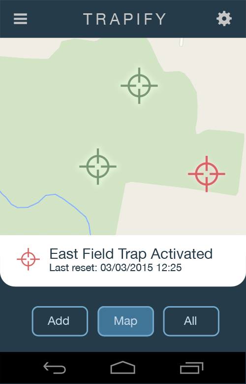
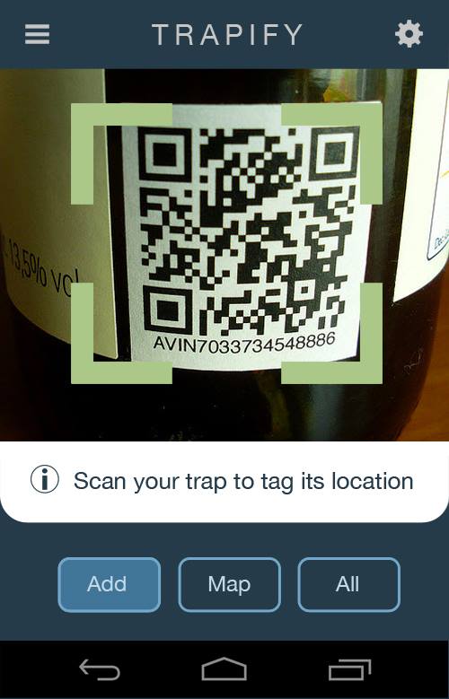
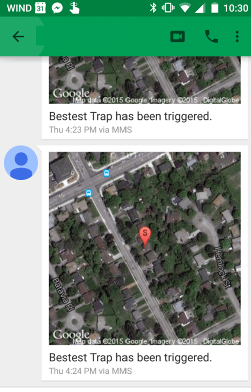
Software
The software side of the project consists of a mobile app and a base station. The QR code on each trap is scanned using the mobile app, allowing the location of each trap to be stored in the database. When the trap is sprung, a detailed text message is sent to the farmer's phone. The photos below show the UI in action.